
Pressure context
State the operating pressure and cycling conditions.
FLUID-SYSTEM COMPONENTS
Align ports, sealing surfaces and inspection requirements before machining.
Discuss your application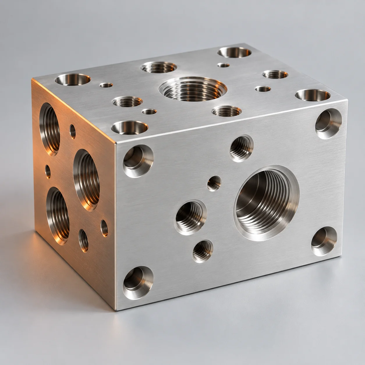
Keep the application and acceptance criteria in the same brief.
State the operating pressure and cycling conditions.
Identify the liquid or gas and exposure.
Specify thread type, port form and interfaces.
Define critical dimensions and checks.
Identify the features that locate, seal or connect the component.
State location, orientation and connection standards.
Define the surface condition and mating features.
Discuss internal edges, cleaning and flow paths.

Keep review, machining, finishing and verification connected.
Confirm the drawing, material and key interfaces.
Agree access, setups and the machining scope.
Define edge condition and surface requirements.
Review critical dimensions, threads and sealing faces.
Review the actual medium, service conditions and material specification.
| Material | Typical considerations | Trade-offs | Review inputs |
|---|---|---|---|
| Aluminum | Weight, machinability and application | Grade, strength and exposure requirements | Environment, pressure and finish |
| Stainless steel | Corrosion and mechanical requirements | Machining approach and cost factors | Medium, grade and temperature |
| Brass | Geometry, compatibility and connections | Confirm compatibility and restrictions | Medium and regulatory requirements |
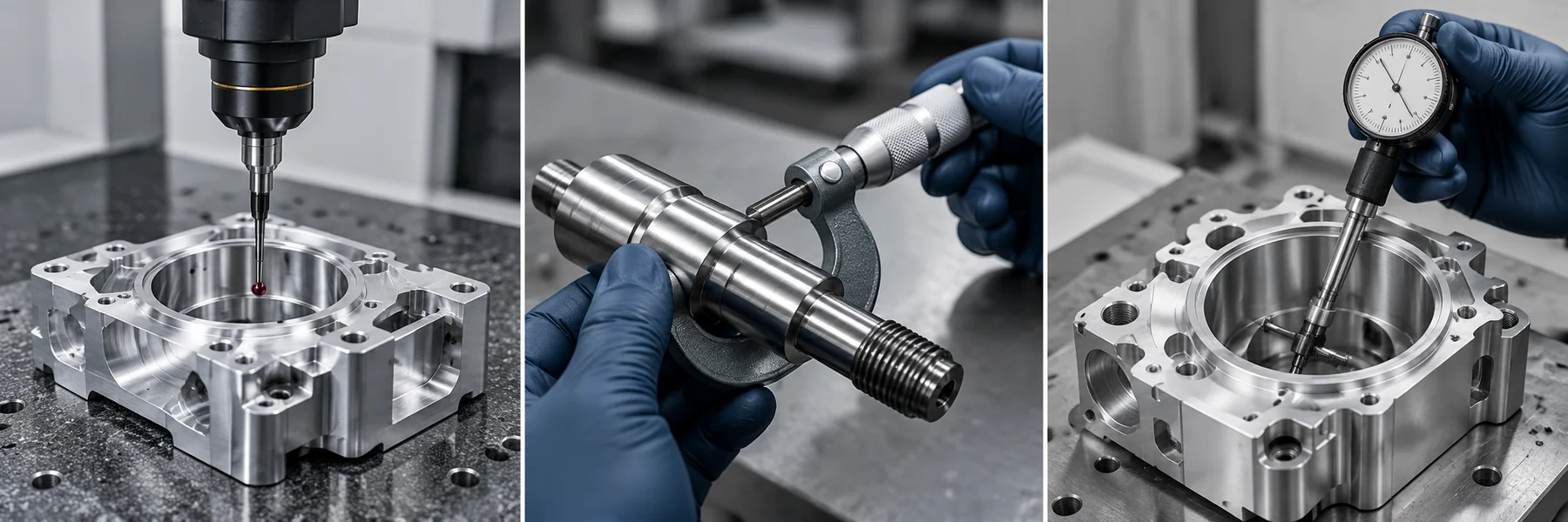
Agree the inspection features and records for your component.
| Feature | Review scope |
|---|---|
| 1 | Overall geometry |
| 2 | Ports / bores |
| 3 | Sealing surfaces |
| 4 | Threads |
Link datums and features to the drawing.
Review edge condition and sealing surfaces.
Confirm the connection form and mating requirements.
Agree the required records and packing details as part of your project.
Identify the approved drawing and revision.
Agree the material documentation required.
Define the features and records to review.
Confirm protection, identification and packing needs.
Share your drawing and the requirements that matter to your application.
Demo inquiry — email delivery is not connected.
QUESTIONS BEFORE RELEASE
Share your current drawing and 3D model using the contact form. Identify revision, units, material and the features that control fit.
The material, process, quantity, inspection scope and release conditions are agreed for the actual part before work proceeds.