Engineering fit
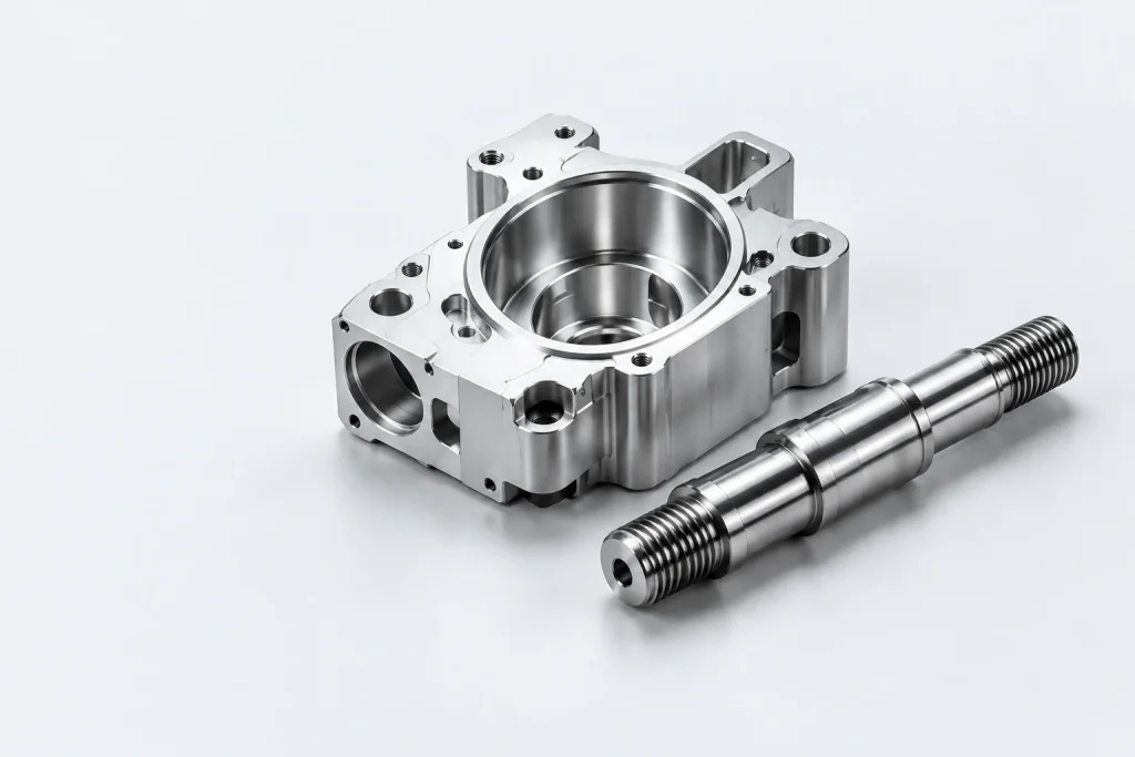
Define bearing seats, locating faces and fastener patterns against a clear datum scheme.
INDUSTRIES / ROBOTICS & AUTOMATION
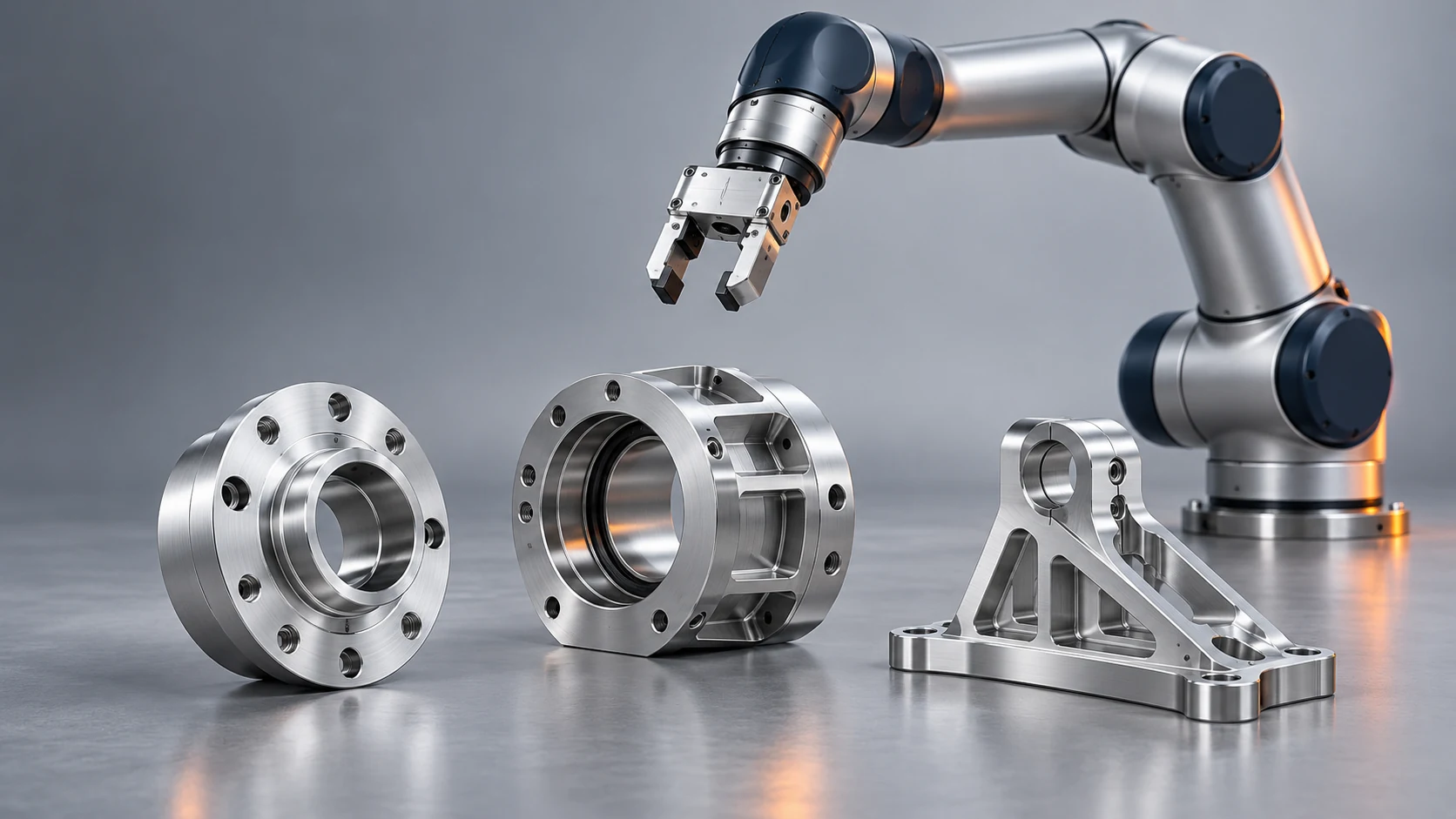
Custom machined components for end-of-arm tooling, robot joints, sensor mounts and automation fixtures. Bring the drawing, mating interfaces and operating conditions together to define the next prototype or repeat build.
Define bearing seats, locating faces and fastener patterns against a clear datum scheme.
Separate prototype quantity, repeat demand and material or finishing alternatives in the RFQ.
Identify the features and records needed for assembly approval, rather than relying on appearance.
Explore typical component functions before discussing the drawing. These visual examples help identify the mating details, fit requirements and finishing decisions that belong in your project brief.
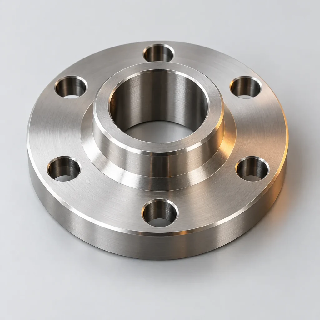
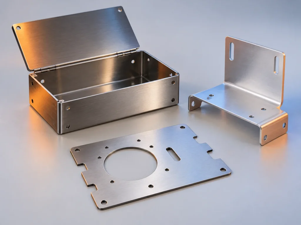
Connect a robot wrist to a tool or fixture. Review the locating diameter, bolt pattern, fastener access and the available operating envelope together.

Locate rotating or sliding elements within a housing. Specify the mating part, fit, surface condition and any coating allowance that affects the finished interface.
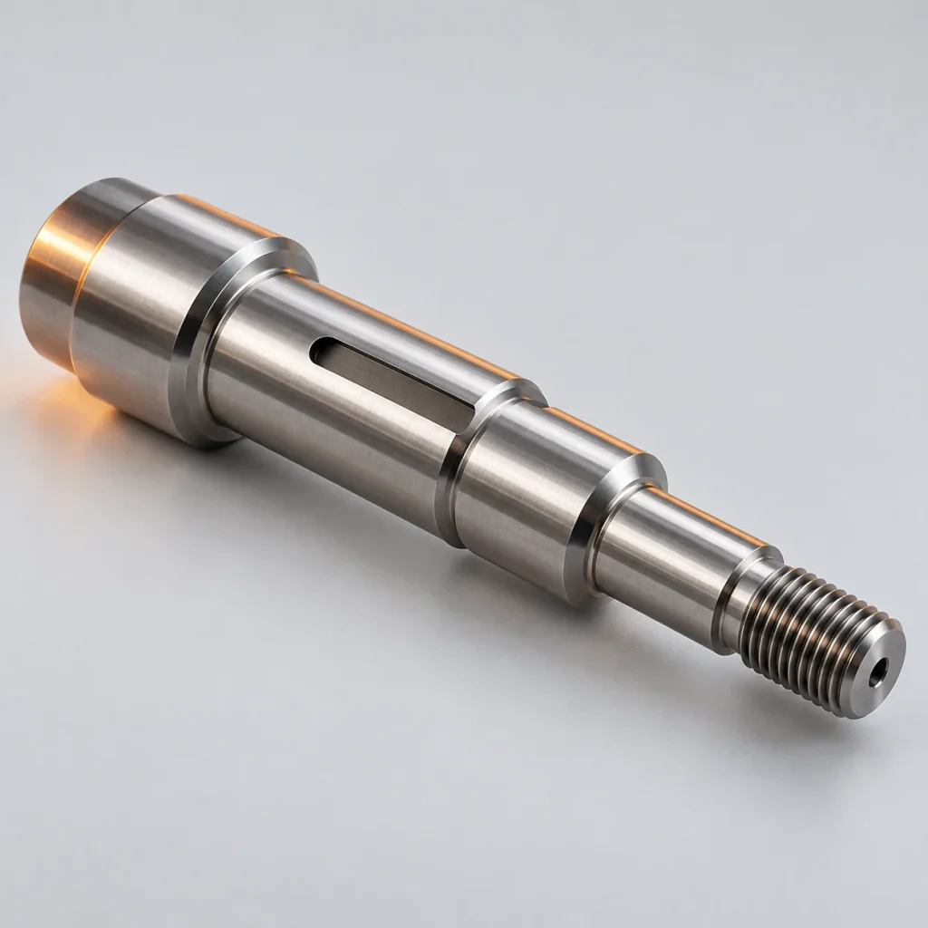
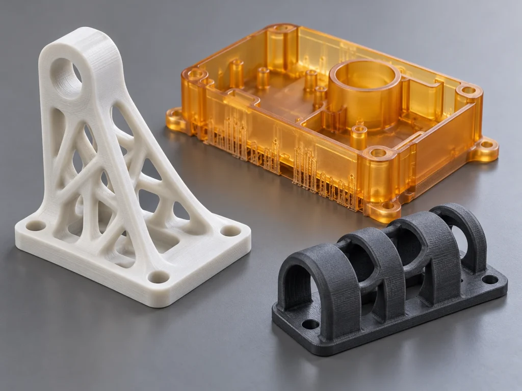
Bring shoulders, journals and coupling features into one datum scheme. Identify the functional fits and which dimensions require inspection after finishing.
A robotics component works within a larger assembly. A gripper adapter connects the robot wrist to the tool; a joint housing locates bearings and drive components; a camera bracket holds a sensor in a defined position. For mobile robots, chassis interfaces and mounting plates also need to suit the equipment and environment around them.
Share the mounting drawing, datum references, operating loads and available envelope. For end-of-arm parts, include the tool and workpiece mass information needed by your robot integrator. Component manufacture follows the approved drawing; robot payload verification, controls and system safety remain part of the integration scope.
Use the following as a starting point. Exact grade, condition, stock availability and finishing compatibility are confirmed for the individual drawing.
| Material family | Where it may fit | What to confirm |
|---|---|---|
| Aluminum alloys | Lightweight brackets, adapter plates and housings. | Stiffness, thread engagement, wear interfaces and dimensions after anodizing. |
| Steel or stainless steel | Shafts, locating features and components needing wear or environmental resistance. | Mass, exact alloy, heat treatment, corrosion exposure and final surface condition. |
| Engineering plastics | POM or other specified polymers for guides, spacers and contact parts. | Load, temperature, moisture, creep and any chemical or cleaning exposure. |
Reducing weight can change wall thickness, workholding and inspection access. A lower-cost stock choice may also change the amount of machining or finishing required. Keep these trade-offs visible before approving a design change. Explore the material library.
APPLICATIONS IN CONTEXT

Gripper fingers, tool adapters and fixture plates connect the robot to the task. Include the workpiece geometry, mating interface, tool mass and cable clearance in the component review.
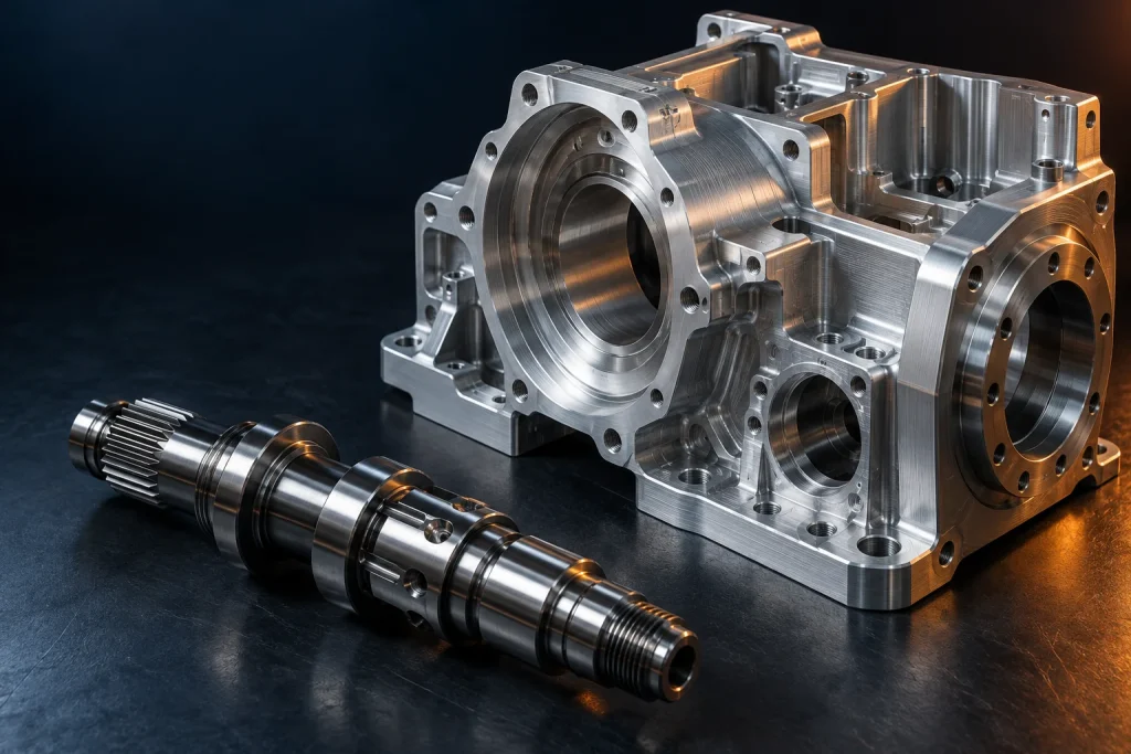
Housings locate bearings, shafts and drive components. Define the datum relationship between bores, shoulders and cover faces, with inspection access and assembly sequence in mind.

Chassis plates, camera brackets and protective interfaces position equipment on a moving platform. Review mounting stability, service access, mass and the operating environment with the integrator.
Provide a 3D model, matching dimensioned drawing, material, quantity and application context. Mark functional interfaces and any unresolved design choices.
A clear drawing revision and RFQ scope.
Discuss tool access, holding, thin sections, finish allowance and inspection access. Confirm proposed alternatives and any geometry changes with the design owner.
An agreed scope for quotation and manufacture.
Use the sample for the defined fit or functional review. Record assembly findings against the drawing; identify changes explicitly instead of carrying them in informal messages.
Documented acceptance or a controlled revision.
Confirm the approved files, material condition, finish, inspection scope and packing requirements for the repeat order. Recheck the scope if quantity or operating conditions change.
A repeat-build package with agreed delivery requirements.
Choose inspection requirements from the function of the part. The drawing should distinguish critical fits from general clearance features and identify whether acceptance applies before or after finishing. Any report, material record, sampling plan or special test must be agreed in the quotation.
For end-of-arm tooling, the robot manufacturer’s documentation treats mounting, mass distribution and integration as system-level considerations. Machined part inspection alone does not establish robot positioning accuracy, payload capability or application safety. The robot builder or integrator remains responsible for validating the complete system.
| Requirement | Specification / review basis |
|---|---|
| Location & mating fits | Datum references, bearing or register diameters, locating faces, hole positions and the defined mating condition. |
| Finish & treatment | Surface requirements, deburring, protected contact faces, masking and dimensions in the final treated condition. |
| Sample approval & records | Features to report, sample quantity, inspection method and any requested material or treatment documentation. |
| Identification & protection | Part number, drawing revision and quantity; protect locating faces, bores and threads during packing and transport. |
QUESTIONS BEFORE RELEASE
Submit drawings for custom adapter flanges, gripper fingers, joint or drive housings, shafts, sensor brackets and fixtures. Feasibility depends on the geometry, material, finish and acceptance requirements. These examples are component applications, not a catalog of complete robots.
Provide the exact robot model, the current wrist or tool interface drawing and the mating tool details. Hole patterns, locating features, fasteners and available clearance must be checked against those documents. Compatibility is confirmed for the specific design, not inferred from a robot brand name.
A prototype can answer a fit, assembly or functional question. Before a repeat order, confirm which material, finish, inspection and documentation requirements represent the intended production condition. Any drawing change needs a controlled revision and renewed approval where appropriate.
Identify the functional relationship on the drawing, with datums, tolerance and required finish. State whether the requirement applies after coating or heat treatment. Avoid applying a tight tolerance to every feature when only a few interfaces control the assembly.
Include the current STEP file and drawing, material and condition, sample or batch quantity, finish, critical dimensions and delivery needs. Add the mating interface, operating environment and inspection requirements. If some details are undecided, identify them as review questions.
CONTINUE YOUR REVIEW
LET’S TALK ABOUT YOUR PROJECT
Share the drawing revision, robot or tool interface, material, quantity and critical fits. Include the operating environment and the records needed for approval.
Demo inquiry — email delivery is not connected.